Next: 6.2 Illustrative frame problem Up: 6. The EST method Previous: 6. The EST method
Consider solving a boundary value problem with the EST method. The second-order analysis is a nonlinear problem and the superposition of deflections cannot be applied. Axial forces are generally not known at the outset of a frame analysis. A set of axial forces of the frame members is determined as a linear structure. At the second iteration, the axial forces from the first iteration are used. If the axial forces obtained by the second iteration differ greatly from the values of the first iteration, the calculated values are used to find new values and the analysis is repeated.
As can be seen from the computing diary excerpt 6.1, the axial forces of the frame elements (given in Fig. 6.7), obtained in the third iteration, do not differ from the values of the second iteration.
SIvec =
         Linear     1         2         3         4
  1    -824.978  -828.823  -828.821  -828.821  -828.821
  2     -25.760   -21.535   -21.499   -21.499   -21.499
  3    -775.104  -773.182  -773.186  -773.186  -773.186
  4     -79.661   -77.786   -77.769   -77.769   -77.769
  5    -739.918  -737.994  -737.993  -737.993  -737.993
In excerpt 6.2 from the computing diary, an iteration for the support reactions of the frame from Fig. 6.7 is shown.
Support_Reactions =
               Linear     1         2         3         4
  Cx           25.760    21.535    21.499    21.499    21.499
  Cz         -824.978  -828.823  -828.821  -828.821  -828.821
  Cx           53.901    56.251    56.270    56.270    56.270
  Cz         -775.104  -773.182  -773.186  -773.186  -773.186
  Cy(moment) -138.774  -157.125  -157.134  -157.134  -157.134
  Cx          130.339   132.214   132.231   132.231   132.231
  Cz         -739.918  -737.994  -737.993  -737.993  -737.993
  Cy(moment) -220.868  -239.506  -239.508  -239.508  -239.508
|
|
Let us start by assembling a system of non-symmetric sparse equations
This collection of boundary problem equations (6.1) is assembled
and solved by the GNU Octave function Lahe2FrameDFIm.m
(p. ![]() ).
).
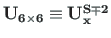
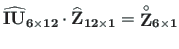
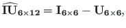
The basic equations of a frame are defined as
 and
and
 are expressed as
 is the transfer matrix given with Eqs. (5.110) and
(5.111) at
is the transfer matrix given with Eqs. (5.110) and
(5.111) at  (Sign Convention 2);
 ,
,
 are the vectors of displacements and forces
at the end and at the beginning of the element, respectively; the loading vector
are the vectors of displacements and forces
at the end and at the beginning of the element, respectively; the loading vector
 is given with Eqs. (5.112), (5.113), (5.114), and (5.115);
 is a unit matrix
  for the frame element.
Equilibrium equations at beam joints and joint equilibrium equations are discussed in sections 2.2 and 2.3, side conditions and restrictions on support displacements are dealt with in sections 2.4 and 2.5.
Inserting the system of the basic equations (6.2) into the system Eq. (6.1) is shown in excerpt 6.1 of the program.
andres
![\begin{lstlisting}[frame=singele,framerule=0pt]{}
IIv=0;
IJv=0;
...](img704.png)

![$\displaystyle \mathbf{\widehat{Z}_{12\times 1}} =
\left[\begin{array}{c}
\mathbf{Z_{L}} \\
\mathbf{Z_{A}}
\end{array}\right]$](img707.png)