Next: 3.4 Illustrative continuous beam Up: 3. Statically indeterminate problems Previous: 3.2 Illustrative frame problem
 and the two
spans are of similar length:
and the two
spans are of similar length:
 . The column 1-2 of length
 is loaded with a uniform load
 .
The rafter 2-4 is subjected to a vertical uniform load
.
The rafter 2-4 is subjected to a vertical uniform load
 . The column 3-4 of length
 carries a concentrated load
 . The beam 3-5 is loaded with a vertical uniform load
 .
.
 and the rafter flexural rigidity
 (
(
 ); the axial rigidity of the column
 and that of the rafter
 ; the shear rigidity of the column
 and that of the rafter
 .
.
We wish to compute the displacements, reactions, internal forces, and draw the axial force, shear force and bending moment diagrams.
Problem Solving.
To solve the problem, the EST method is used.
Since the element loads are described in local coordinates, we assume the directions of the local coordinates
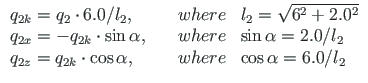
shown in Fig. 3.16. Now let us express the vertical uniform load,
 ,
in local coordinates (
,
in local coordinates ( - projection onto the x-axis,
  - projection onto the z-axis):
 is the length of the rafter in local coordinates.
As in example 3.1, we carry out the following steps of calculations.
1. Input data for the GNU Octave program spESTframe77LaheWFI.m are shown in excerpts from the program: element and nodal loads - excerpt 3.7; nodal coordinates - excerpt 3.8; element properties, topology and hinges - excerpt 3.9.
 Number_of_frame_nodes=6
 Number_of_elements=7
 Number_of_support_reactions=3
 spNNK=12*Number_of_elements+Number_of_support_reactions;
 Number_of_unknowns=spNNK
 Displacements and forces calculated on parts of the element 'Nmitmeks'.
 Nmitmeks=4
 Lp=12.0; # graphics axis
# --- Element properties ---
EIp=20000 # kN/m^2 EIr=40000 # kN/m^2 # EAp=4.6*10^6 EAp=4.6*10^15; #EAr=6.8*10^6; EAr=6.8*10^15 GAp=0.4*EAp; GAr=0.4*EAr; F3=12; q1=4.0; q2=8.0; q3=8.0; L2x=sqrt(6.0^2+2.0^2); # length of the element sinA2=2.0/L2x; cosA2=6.0/L2x; qz2v=q2*6.0/L2x; # load/length of the element qz1=q1; qz7=q3; qz2=qz2v*cosA2; # projection onto z-axis qx2=-qz2v*sinA2; # projection onto x-axis |
baasi0=EIp/5.0  # scaling multiplier for displacements
#baasi0=1.0;

#Element load  in local coordinates
#  qz     qx     qA      qL
# Uniformly distributed load in local coordinate z and x directions
LoadsqONelement=4;
esQkoormus=zeros(LoadsqONelement,4,ElementideArv);
esQkoormus(1,1:4,1)=[qz1 0.0 0.0 5.0];
esQkoormus(1,1:4,2)=[qz2 qx2 0.0 L2x];
esQkoormus(1,1:4,3)=[0.0 0.0 0.0 7.0];
esQkoormus(1,1:4,4)=[0.0 0.0 0.0 L2x];
esQkoormus(1,1:4,5)=[0.0 0.0 0.0 5.0];
esQkoormus(1,1:4,6)=[0.0 0.0 0.0 6.0];
esQkoormus(1,1:4,7)=[qz7 0.0 0.0 6.0];
#
# Point load in local coordinate z and x directions  kN
#  Fz, Fx, aF (coordinate of the point of force application)
LoadsF_on_Element=5;
esFjoud=zeros(LoadsF_on_Element,2,ElementideArv);
esFjoud(1,1:3,1)=[0.0 0.0 0.0];
esFjoud(1,1:3,2)=[0.0 0.0 0.0];
esFjoud(1,1:3,3)=[12.0 0.0 4.0];
esFjoud(1,1:3,4)=[0.0 0.0 0.0];
esFjoud(1,1:3,5)=[0.0 0.0 0.0];
esFjoud(1,1:3,6)=[0.0 0.0 0.0];
esFjoud(1,1:3,7)=[0.0 0.0 0.0];
#
#Node forces in global coordinates
# sSolmF(forces,1,nodes); forces=[Fx; Fz; My]
sSolmF = zeros(3,1,SolmedeArv);
#sSolmF(:,1,1)= 0.0
#sSolmF(:,1,2)= 0.0
#sSolmF(:,1,3)= 0.0
#sSolmF(:,1,4)= 0.0
#sSolmF(:,1,5)= 0.0
#sSolmF(:,1,6)= 0.0
#
#s1F(1,1,1)=0.0;  # force Fz
#s1F(2,1,1)=0.0;  # force Fz
#s1F(3,1,1)=0.0;  # force My

# Support shift - tSiire#
# Support shift is multiplied by scaling multiplier
tSiire = zeros(3,1,SolmedeArv);
#tSiire(1,1,1)= 0.0
#tSiire(2,1,1)= 0.01*baasi0
#tSiire(2,1,5)= 0.0
#==========
#     Nodal coordinates
#==========
krdn=[#  x       z
        0.0     0.0;    # node 1
        0.0    -5.0;    # node 2
        6.0     0.0;    # node 3
        6.0    -7.0;    # node 4
       12.0     0.0;    # node 5
       12.0    -5.0];   # node 6
#==========
#
#==========
#  Restrictions on support displacements (on - 1, off - 0)
# Support  No   u   w  fi
#==========
tsolm=[1     1 1 0;   % node 1
       5     0 1 0];  % node 5
#==========
# ------------- Element properties, topology and hinges ---------
elasts=[# Element properties
#            n2 - end of the element
#                  n1 - beginning of the element
#                       N, Q, M -  hinges at the end of the element
#                                N, Q, M -  hinges at the beginning of the element
#
 EIp EAp GAp   2     1    0 0 0    0 0 1;    % element 1
 EIr EAr GAr   4     2    0 0 0    0 0 0;    % element 2
 EIp EAp GAp   4     3    0 0 0    0 0 0;    % element 3
 EIr EAr GAr   6     4    0 0 0    0 0 0;    % element 4
 EIp EAp GAp   5     6    0 0 1    0 0 0;    % element 5
 EIr EAr GAr   3     1    0 0 0    0 0 1;    % element 6
 EIr EAr GAr   5     3    0 0 1    0 0 0];   % element 7
# 1 - hinge 'true' (axial, shear, moment hinges)
#
2. Assembling and solving the boundary problem equations (3.11), carried out by the function LaheFrameDFIm(baasi0,Ntoerkts,esQkoormus,esFjoud, sSolmF,tsolm,tSiire, krdn,selem). The program has numbered the displacements and forces of the frame element ends as shown in Fig. 3.16. The unscaled initial parameter vectors of the elements are shown in excerpt 3.7 from the computing diary.
-------- Scaling multiplier for displacements = 1/baasi0 --------

============================================================================
 Unscaled initial parameter vector
Element    u          w          fi             N          Q          M
  No
----------------------------------------------------------------------------
   1  -0.000e+00   0.000e+00  -2.842e-03       37.423     -6.458     0.000
   2   1.204e-02   4.013e-03  -2.972e-03       24.682    -31.221    17.712
   3  -1.021e-02   2.254e-14  -1.220e-03      -12.982    -14.240    37.191
   4   1.850e-02   4.598e-03   5.078e-04       18.172     18.775   -62.236
   5   2.561e-14  -1.950e-02   8.096e-04       23.558    -11.302    56.510
   6   0.000e+00   0.000e+00  -1.943e-03      -25.542     -2.410     0.000
   7   2.254e-14   1.021e-02  -1.220e-03      -11.302    -15.392   -51.650

----------------------------------------------------------------------------
The support reactions of the frame in global coordinates are shown in excerpt 3.8 from the computing diary.
Support reactions begin from row X: 85
===========================================
 No         X        Node    Cx <=> 1
                             Cz <=> 2
                             Cy <=> 3
-------------------------------------------
 85   -3.200000e+01    1         1
 86   -3.983333e+01    1         2
 87   -5.616667e+01    5         2
--------------------------------------------
3. Output: the element displacements and forces determined by the transfer matrix are shown in excerpt 3.9 from the computing diary. The diagrams of the bending moment M, shear force Q and axial force N of the frame EST77 are shown in Fig. 3.17.
Here, the values are determined with the axial stiffness
 (with negligible axial deformations, the values coincide with these found with the force method, see
[Lah12] 3.1 Fig. 9.23 on p. 243).
(with negligible axial deformations, the values coincide with these found with the force method, see
[Lah12] 3.1 Fig. 9.23 on p. 243).
#=================================================================================
 Element displacements and forces determined by transfer matrix
#=================================================================================
Displacements and forces of element no 1 of length 5.000 m
The element is divided into 4 parts
 displacement u -  0.00000e+00 -1.01694e-14 -2.03388e-14 -3.05082e-14 -4.06777e-14
 displacement w -  0.00000e+00  8.48273e-02  1.30835e+00  6.59962e+00  2.08408e+01
 rotation    fi - -2.84172e-03 -2.63006e-01 -2.08517e+00 -7.03182e+00 -1.66655e+01
 normal force N -  -37.42345   -37.42345   -37.42345   -37.42345  -37.42345
 shear force  Q -    6.45764     1.45764    -3.54236    -8.54236  -13.54236
 moment force M -    0.00000     4.94705     3.64410    -3.90885  -17.71180
----------------------------------------------------------------------------
Displacements and forces of element no 2 of length 6.32456 m
The element is divided into 4 parts
 displacement u -  1.20390e-02  1.20390e-02  1.20390e-02  1.20390e-02  1.20390e-02
 displacement w -  4.01301e-03  1.33739e-01  2.01215e+00  1.01372e+01  3.20068e+01
 rotation    fi - -2.97237e-03 -3.19016e-01 -2.53113e+00 -8.53667e+00 -2.02330e+01
 normal force N -  -24.68175   -20.88701   -17.09228   -13.29755   -9.50281
 shear force  Q -   31.22053    19.83633     8.45213    -2.93207  -14.31626
 moment force M -  -17.71180    22.65220    45.01619    49.38019   35.74419
----------------------------------------------------------------------------
Displacements and forces of element no 3 of length 7.000 m
The element is divided into 4 parts

 displacement u - -1.02109e-02 -1.02109e-02 -1.02109e-02 -1.02109e-02 -1.02109e-02
 displacement w -  2.25374e-14  4.34616e-03  1.05712e-02  7.96109e-01  1.08134e+01
 rotation    fi - -1.21985e-03 -3.38376e-03 -3.36712e-03 -1.87617e+00 -1.07968e+01
 normal force N -   12.98177    12.98177    12.98177    12.98177   12.98177
 shear force  Q -   14.24039    14.24039    14.24039     2.24039    2.24039
 moment force M -  -37.19081   -12.27013    12.65055    22.57123   26.49192
----------------------------------------------------------------------------
Displacements and forces of element no 4 of length 6.32456 m
The element is divided into 4 parts
 displacement u - 1.84970e-02 1.84970e-02  1.84970e-02  1.84970e-02  1.84970e-02
 displacement w - 4.59761e-03 2.70421e-03 -5.45432e-04 -3.91437e-03 -6.16566e-03
 rotation    fi - 5.07846e-04 1.75676e-03  2.22336e-03  1.90766e-03  8.09646e-04
 normal force N -  -18.17178   -18.17178   -18.17178   -18.17178  -18.17178
 shear force  Q -  -18.77538   -18.77538   -18.77538   -18.77538  -18.77538
 moment force M -   62.23611    32.54962     2.86313   -26.82336  -56.50985
----------------------------------------------------------------------------

Displacements and forces of element no 5 of length 5.000 m
The element is divided into 4 parts
 displacement u -  2.56069e-14  1.92051e-14  1.28034e-14  6.40172e-15 -3.15544e-30
 displacement w - -1.94975e-02 -1.84861e-02 -1.41636e-02 -7.63366e-03 -3.25087e-14
 rotation    fi -  8.09646e-04 -2.28074e-03 -4.48815e-03 -5.81260e-03 -6.25409e-03
 normal force N -  -23.55832   -23.55832   -23.55832   -23.55832  -23.55832
 shear force  Q -   11.30197    11.30197    11.30197    11.30197   11.30197
 moment force M -  -56.50985   -42.38239   -28.25493   -14.12746    0.00000
----------------------------------------------------------------------------
Displacements and forces of element no 6 of length 6.000 m
The element is divided into 4 parts
 displacement u -  0.00000e+00  5.63434e-15  1.12687e-14  1.69030e-14  2.25374e-14
 displacement w -  0.00000e+00  2.89162e-03  5.64769e-03  8.13265e-03  1.02109e-02
 rotation    fi - -1.94281e-03 -1.89763e-03 -1.76207e-03 -1.53614e-03 -1.21985e-03
 normal force N -   25.54236    25.54236    25.54236    25.54236   25.54236
 shear force  Q -    2.40988     2.40988     2.40988     2.40988    2.40988
 moment force M -    0.00000     3.61482     7.22964    10.84447   14.45929
----------------------------------------------------------------------------
Displacements and forces of element no 7 of length 6.000 m
The element is divided into 4 parts
 displacement u -  2.25374e-14  2.50305e-14  2.75235e-14  3.00166e-14  3.25097e-14
 displacement w -  1.02109e-02  1.23428e-01  1.80884e+00  9.11559e+00  2.87928e+01
 rotation    fi - -1.21985e-03 -2.99640e-01 -2.39748e+00 -8.09475e+00 -1.91914e+01
 normal force N -   11.30197    11.30197    11.30197    11.30197   11.30197
 shear force  Q -   15.39165     3.39165    -8.60835   -20.60835  -32.60835
 moment force M -   51.65010    65.73758    61.82505    39.91253    0.00000
----------------------------------------------------------------------------
Forces of element  3  at x = 4.00 m
 displacement u - -1.02109e-02
 displacement w -  1.21608e-02
 rotation    fi - -2.96185e-03
 normal force N -   12.98177
 shear force  Q -    2.24039
 moment force M -   19.77075
-----------------------------------
Forces of element  3  at x = 3.99 m
 displacement u - -1.02109e-02
 displacement w -  1.21608e-02
 rotation    fi - -2.96185e-03
 normal force N -   12.98177
 shear force  Q -   14.24039
 moment force M -   19.77073
-----------------------------------
Consider now a static equilibrium of the frame shown in Fig. 3.18 a.
We project the forces onto the X and Z axes.
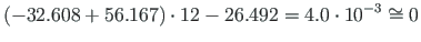
The sum of the moments and the moments of the forces acting about point a (shown in Fig. 3.18 a) are:
Consider next a static equilibrium of the frame shown in Fig. 3.18 b.
Let us project the forces onto the X and Z axes.
Now, the sum of the moments and the moments of the forces acting about point a (shown in Fig. 3.18 b) are:
The elements and the sparsity pattern of matrix spA of the frame EST77 are shown in Figs. 3.19 and 3.20, respectively.
![\includegraphics[width=90mm]{joonised/JoumVar7_1.eps}](img376.png)

![\includegraphics[width=110mm]{joonised/JoumVar7_2.eps}](img382.png)
![\includegraphics[width=0.97\textwidth]{joonised/JoumVar9_6.eps}](img383.png)
![\includegraphics[width=1.0\textwidth]{joonised/JoumVar9_7.eps}](img384.png)


![\includegraphics[width=0.84\textwidth]{joonised/RaamEST77en.eps}](img396.png)
![\includegraphics[width=0.75\textwidth]{joonised/RaamEST77_sparse.eps}](img397.png)