Next: 3.5 Illustrative truss problem Up: 3. Statically indeterminate problems Previous: 3.3 Illustrative frame problem
 and the shear rigidity
 . The dead loading is a uniform load
 (load case 1).
The beam is also subjected to a live loading (load cases 2 and 3). The beam is simultaneously loaded with forces
(load case 1).
The beam is also subjected to a live loading (load cases 2 and 3). The beam is simultaneously loaded with forces
 and
and
 (load case 2). In load case 3, it is
loaded with force
(load case 2). In load case 3, it is
loaded with force
 .
.
1. Input data for the GNU Octave program spESTbeamLaheWFI.m are shown in excerpts from the program: element and nodal loads - excerpt 3.10; nodal coordinates - excerpt 3.11; element properties, topology and hinges - excerpt 3.12.
 Number_of_beam_nodes=5
 Number_of_elements=4
 Number_of_support_reactions=5
 spNNK=8*Number_of_elements+Number_of_support_reactions;
 Number_of_unknowns=spNNK
 Displacements and forces calculated on parts of the element 'Nmitmeks'.
 Nmitmeks=5
 Lp=24.0; # graphics axis
# --- Element properties ---
EI=20000 # kN/m^2
GA=1.0*10^15
F1=60;
F2=40;
F3=80;
qz=12.0;
baasi0=EI/8.0  # scaling multiplier for displacements
#baasi0=1.0;
# ---- load variants -----
load_variant=1
#load_variant=2
#load_variant=3
 koormusvariant=load_variant
#koormusvariant=2
#koormusvariant=3
switch (koormusvariant)
case{1}
#
disp(' Load variant 1 ')
#disp(' Element load  in local coordinates ')
# Uniformly distributed load in local coordinate z direction
LoadsqONelement=4;
esQkoormus=zeros(LoadsqONelement,3,ElementideArv);
esQkoormus(1,1:3,1)=[qz 0.0 8.0];
esQkoormus(1,1:3,2)=[qz 0.0 8.0];
esQkoormus(1,1:3,3)=[qz 0.0 6.0];
esQkoormus(1,1:3,4)=[qz 0.0 2.0];
# Point load in local coordinate z direction
LoadsF_on_Element=5;
# 2 - Fz, aFz (coordinate of the point of force Fz application)
esFjoud=zeros(LoadsF_on_Element,2,ElementideArv);
esFjoud(1,1:2,1)=[0.0 8.0];
esFjoud(1,1:2,2)=[0.0 8.0];
esFjoud(2,1:2,2)=[0.0 8.0];
esFjoud(1,1:2,3)=[0.0 6.0];
esFjoud(1,1:2,4)=[0.0 2.0];
#disp(' Node forces in global coordinates ')
#disp(' Node 1 load ')
# sSolmF(forces,1,nodes); forces=[Fz; My]
sSolmF = zeros(2,1,SolmedeArv);
#sSolmF(1,1,1)= 0.0 # force Fz
#sSolmF(2,1,1)= 0.0 # force My
#sSolmF(:,1,2)= 0.0
#sSolmF(:,1,3)= 0.0
#sSolmF(:,1,4)= 0.0
#sSolmF(:,1,5)= 0.0
# Support shift - tSiire#
# Support shift is multiplied by scaling multiplier
tSiire = zeros(2,1,SolmedeArv);
#tSiire(:,1,1)= 0.0
#tSiire(2,1,1)= 0.01*baasi0
#tSiire(:,1,2)= 0.0
#tSiire(:,1,3)= 0.0
#tSiire(:,1,4)= 0.0
#tSiire(:,1,5)= 0.0
case{2}
disp(' Load variant 2 ')
#disp(' Element load  in local coordinates ')
# Uniformly distributed load in local coordinate z direction
LoadsqONelement=4;
esQkoormus=zeros(LoadsqONelement,3,ElementideArv);
esQkoormus(1,1:3,1)=[0.0 0.0 8.0];
esQkoormus(1,1:3,2)=[0.0 0.0 8.0];
esQkoormus(1,1:3,3)=[0.0 0.0 6.0];
esQkoormus(1,1:3,4)=[0.0 0.0 2.0];
# Point load in local coordinate z direction
LoadsF_on_Element=5;
# 2 - Fz, aFz (coordinate of the point of force Fz application)
esFjoud=zeros(LoadsF_on_Element,2,ElementideArv);
esFjoud(1,1:2,1)=[0.0 8.0];
esFjoud(1,1:2,2)=[F1  1.6];
esFjoud(2,1:2,2)=[F2  4.8];
esFjoud(1,1:2,3)=[0.0 6.0];
esFjoud(1,1:2,4)=[0.0 2.0];
#disp(' Node forces in global coordinates ')
#disp(' Node 1 load ')
# sSolmF(forces,1,nodes); forces=[Fz; My]
sSolmF = zeros(2,1,SolmedeArv);
#sSolmF(1,1,1)= 0.0 # force Fz
#sSolmF(2,1,1)= 0.0 # force My
#sSolmF(:,1,2)= 0.0
#sSolmF(:,1,3)= 0.0
#sSolmF(:,1,4)= 0.0
#sSolmF(:,1,5)= 0.0
# Support shift - tSiire#
# Support shift is multiplied by scaling multiplier
tSiire = zeros(2,1,SolmedeArv);
#tSiire(:,1,1)= 0.0
#tSiire(2,1,1)= 0.01*baasi0
#tSiire(:,1,2)= 0.0
#tSiire(:,1,3)= 0.0
#tSiire(:,1,4)= 0.0
#tSiire(:,1,5)= 0.0
case{3}
disp(' Load variant 3 ')
#disp(' Element load  in local coordinates ')
# Uniformly distributed load in local coordinate z direction
LoadsqONelement=4;
esQkoormus=zeros(LoadsqONelement,3,ElementideArv);
esQkoormus(1,1:3,1)=[0.0 0.0 8.0];
esQkoormus(1,1:3,2)=[0.0 0.0 8.0];
esQkoormus(1,1:3,3)=[0.0 0.0 6.0];
esQkoormus(1,1:3,4)=[0.0 0.0 2.0];
# Point load in local coordinate z direction
LoadsF_on_Element=5;
# 2 - Fz, aFz (coordinate of the point of force Fz application)
esFjoud=zeros(LoadsF_on_Element,2,ElementideArv);
esFjoud(1,1:2,1)=[0.0 8.0];
esFjoud(1,1:2,2)=[0.0 8.0];
esFjoud(2,1:2,2)=[0.0 8.0];
esFjoud(1,1:2,3)=[F3  3.6];
esFjoud(1,1:2,4)=[0.0 2.0];
#disp(' Node forces in global coordinates ')
#disp(' Node 1 load ')
# sSolmF(forces,1,nodes); forces=[Fz; My]
sSolmF = zeros(2,1,SolmedeArv);
#sSolmF(1,1,1)= 0.0 # force Fz
#sSolmF(2,1,1)= 0.0 # force My
#sSolmF(:,1,2)= 0.0
#sSolmF(:,1,3)= 0.0
#sSolmF(:,1,4)= 0.0
#sSolmF(:,1,5)= 0.0
# Support shift - tSiire#
# Support shift is multiplied by scaling multiplier
tSiire = zeros(2,1,SolmedeArv);
#tSiire(:,1,1)= 0.0
#tSiire(2,1,1)= 0.01*baasi0
#tSiire(:,1,2)= 0.0
#tSiire(:,1,3)= 0.0
#tSiire(:,1,4)= 0.0
#tSiire(:,1,5)= 0.0
##
otherwise
disp(' No load variant cases ')
endswitch
##
#==========
#     Nodal coordinates
#==========
krdn=[#  x
        0.0 ; # node 1
        8.0 ; # node 2
       16.0 ; # node 3
       22.0 ; # node 4
       24.0]; # node 5
#==========
#
#==========
#  Restrictions on support displacements (on - 1, off - 0)
# Support  No   w  fi
#==========
tsolm=[1   1 1 ;  # node 1
       2   1 0 ;  # node 2
       3   1 0 ;  # node 3
       4   1 0 ]; # node 4
#==========
# ------------- Element properties, topology and hinges ---------
elasts=[# Element properties
#            n2 - end of the element
#                  n1 - beginning of the element
#                       N, Q, M -  hinges at the end of the element
#                                N, Q, M -  hinges at the beginning of the element
#
   EI  GA    2     1    0 0    0 0;    % element 1
   EI  GA    3     2    0 0    0 0;    % element 2
   EI  GA    4     3    0 0    0 0;    % element 3
   EI  GA    5     4    0 0    0 0];   % element 4
# 1 - hinge 'true' (shear, moment hinges)
#
2. Assembling and solving the boundary problem equations (3.14), carried out by the function LaheBeamDFI(baasi0,Ntoerkts,esQkoormus,esFjoud, sSolmF,tsolm,tSiire, krdn,selem). The program has numbered the displacements and forces of the beam element ends as shown in Fig. 3.22. The unscaled initial parameter vectors of the elements are shown in excerpt 3.10 from the computing diary.
-- Scaling multiplier for displacements = 1/baasi0 ---
============================================================
 Unscaled initial parameter vector
Element      w          fi             Q          M
   No
------------------------------------------------------------
   1   +0.000e+00   +0.000e+00      -47.450     62.533
   2   +0.000e+00   -2.933e-04      -49.650     66.933
   3   +0.000e+00   +1.173e-03      -40.956     53.733
   4   +0.000e+00   +3.133e-04      -24.000     24.000
------------------------------------------------------------
The support reactions of the beam in global coordinates are shown in excerpt 3.11 from the computing diary.
Support reactions begin from row X: 33
===========================================
 No         X        Node    Cz <=> 1
                             Cy <=> 2
-------------------------------------------
 33   -4.745000e+01    1         1
 34   +6.253333e+01    1         2
 35   -9.820000e+01    2         1
 36   -8.730556e+01    3         1
 37   -5.504444e+01    4         1
--------------------------------------------
3. Output
Output of load case 1: the element displacements and forces determined by the transfer matrix are shown in excerpt 3.12 from the computing diary.
The shear force Q and the bending moment diagrams of the beam are shown in Fig. 3.23.
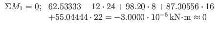
Testing a static equilibrium for the beam
Consider a static equilibrium of the beam shown in Fig. 3.23.
Let us project the forces onto the Z-axis:
#=================================================================================
 Element displacements and forces determined by transfer matrix
#=================================================================================
Displacements and forces of element no 1 of length 8.000 m
The element is divided into 5 parts
 displacement w -  0.000e+00  2.546e-03  5.673e-03 5.560e-03 2.321e-03  1.388e-17
 rotation    fi -  0.000e+00 -2.375e-03 -1.135e-03 1.264e-03 2.364e-03 -2.933e-04
 shear force  Q -    47.450    28.250     9.050    -10.150   -29.350   -48.550
 moment force M -   -62.533    -1.973    27.867     26.987    -4.613   -66.933
----------------------------------------------------------------------------
Displacements and forces of element no 2 of length 8.000 m
The element is divided into 5 parts
 displacement w -  0.000e+00  3.222e-03  7.137e-03 7.475e-03 3.898e-03 -1.388e-17
 rotation    fi - -2.933e-04 -2.880e-03 -1.569e-03 1.182e-03 2.915e-03  1.173e-03
 shear force  Q -    49.650    30.450     11.250    -7.950   -27.150    -46.350
 moment force M -   -66.933    -2.853     30.507    33.147     5.067    -53.733
----------------------------------------------------------------------------
Displacements and forces of element no 3 of length 6.000 m
The element is divided into 5 parts
 displacement w -  0.000e+00 -1.152e-05  1.033e-03 1.461e-03 8.448e-04 6.939e-18
 rotation    fi -  1.173e-03 -7.491e-04 -7.595e-04 1.053e-04 8.085e-04 3.133e-04
 shear force  Q -    40.956    26.556    12.156     -2.244    -16.644   -31.044
 moment force M -   -53.733   -13.227    10.000     15.947      4.613   -24.000
----------------------------------------------------------------------------
Displacements and forces of element no 4 of length 2.000 m
The element is divided into 5 parts
 displacement w - 0.000e+00 -4.149e-05  4.117e-05  1.942e-04  3.793e-04  5.733e-04
 rotation    fi - 3.133e-04 -7.707e-05 -3.139e-04 -4.355e-04 -4.803e-04 -4.867e-04
 shear force  Q -   24.000    19.200     14.400     9.600     4.800      0.000
 moment force M -  -24.000   -15.360     -8.640    -3.840    -0.960      0.000
----------------------------------------------------------------------------
Forces of element  1  at x = 4.000
 displacement w -  6.10667e-03
 rotation    fi -  7.33333e-05
 shear force  Q -   -0.55000
 moment force M -   31.26667
-----------------------------------
Forces of element  2  at x = 1.599
 displacement w -  3.22218e-03
 rotation    fi - -2.88000e-03
 shear force  Q -   30.45001
 moment force M -   -2.85336
-----------------------------------
Forces of element  2  at x = 4.000
 displacement w -   7.86667e-03
 rotation    fi - -2.20000e-04
 shear force  Q -    1.65000
 moment force M -   35.66667
-----------------------------------
Forces of element  2  at x = 4.800
 displacement w -  7.47520e-03
 rotation    fi -  1.18187e-03
 shear force  Q -   -7.95000
 moment force M -   33.14667
-----------------------------------
Forces of element  3  at x = 3.600
 displacement w -  1.46112e-03
 rotation    fi -  1.05333e-04
 shear force  Q -   -2.24444
 moment force M -   15.94667
-----------------------------------
Output of load case 2: the initial parameter vector and support reactions.
-- Scaling multiplier for displacements = 1/baasi0 ---
============================================================
 Unscaled initial parameter vector
Element      w          fi             Q          M
  No
------------------------------------------------------------
   1   +0.000e+00   +0.000e+00       10.752    -28.672
   2   +0.000e+00   -5.734e-03      -65.536     57.344
   3   +0.000e+00   +4.506e-03       -7.509     45.056
   4   +0.000e+00   -2.253e-03        0.000      0.000
------------------------------------------------------------
The support reactions of the beam in global coordinates are shown in excerpt 3.14 from the computing diary.
Support reactions begin from row X: 33
===========================================
 No         X        Node    Cz <=> 1
                             Cy <=> 2
-------------------------------------------
 33   +1.075200e+01    1         1
 34   -2.867200e+01    1         2
 35   -7.628800e+01    2         1
 36   -4.197333e+01    3         1
 37   +7.509333e+00    4         1
--------------------------------------------
The element displacements and forces determined by the transfer matrix are shown in excerpt 3.15 from the computing diary.
The shear force Q and the bending moment diagrams of the beam are shown in Fig. 3.24.
Testing a static equilibrium for the beam
Consider next a static equilibrium of the beam shown in Fig. 3.24.
Let us project the forces onto the Z-axis:
#=================================================================================
 Element displacements and forces determined by transfer matrix
#=================================================================================
Displacements and forces of element no 1 of length 8.000 m
The element is divided into 5 parts
 displacement w - 0.000e+00 -1.468e-03 -4.404e-03 -6.606e-03 -5.872e-03 -6.939e-18
 rotation    fi - 0.000e+00  1.606e-03  1.835e-03  6.881e-04 -1.835e-03 -5.734e-03
 shear force  Q - -10.752    -10.752    -10.752    -10.752    -10.752    -10.752
 moment force M -  28.672     11.469     -5.734    -22.938    -40.141    -57.344
----------------------------------------------------------------------------
Displacements and forces of element no 2 of length 8.000 m
The element is divided into 5 parts
 displacement w -  0.000e+00  1.061e-02  1.718e-02 1.654e-02 8.916e-03  2.776e-17
 rotation    fi - -5.734e-03 -6.128e-03 -1.972e-03 2.892e-03 5.904e-03  4.506e-03
 shear force  Q -   65.536      5.536     5.536   -34.464    -34.464    -34.464
 moment force M -  -57.344     47.514    56.371    65.229     10.086    -45.056
----------------------------------------------------------------------------
Displacements and forces of element no 3 of length 6.000 m
The element is divided into 5 parts
 displacement w - 0.000e+00 -3.893e-03 -5.190e-03 -4.542e-03 -2.595e-03 -6.939e-18
 rotation    fi - 4.506e-03  2.073e-03  1.802e-04 -1.171e-03 -1.982e-03 -2.253e-03
 shear force  Q -    7.509     7.509     7.509      7.509      7.509      7.509
 moment force M -  -45.056   -36.045   -27.034    -18.022     -9.011      0.000
----------------------------------------------------------------------------
Displacements and forces of element no 4 of length 2.000 m
The element is divided into 5 parts
 displacement w -  0.000e+00  9.011e-04  1.802e-03  2.703e-03  3.604e-03 4.506e-03
 rotation    fi - -2.253e-03 -2.253e-03 -2.253e-03 -2.253e-03 -2.253e-03 -2.253e-03
 shear force  Q -    0.000      0.000      0.000      0.000      0.000      0.000
 moment force M -    0.000      0.000      0.000      0.000      0.000      0.000
----------------------------------------------------------------------------
Forces of element  1  at x = 4.000
 displacement w -  -5.73440e-03
 rotation    fi -   1.43360e-03
 shear force  Q - -10.75200
 moment force M - -14.33600
-----------------------------------
Forces of element  2    at x =  1.599
 displacement w -  1.06081e-02
 rotation    fi - -6.12762e-03
 shear force  Q - 65.53600
 moment force M - 47.51353
-----------------------------------
Forces of element  2  at x = 4.000
 displacement w -   1.78347e-02
 rotation    fi -   3.71200e-04
 shear force  Q -   5.53600
 moment force M -  60.80000
-----------------------------------
Forces of element  2  at x = 4.800
 displacement w -   1.65413e-02
 rotation    fi -   2.89178e-03
 shear force  Q - -34.46400
 moment force M -  65.22880
-----------------------------------
Forces of element  3  at x = 3.600
 displacement w -  -4.54164e-03
 rotation    fi -  -1.17146e-03
 shear force  Q -   7.50933
 moment force M - -18.02240
-----------------------------------
Output of load case 3: the initial parameter vector and support reactions.
-- Scaling multiplier for displacements = 1/baasi0 ---
============================================================
 Unscaled initial parameter vector
Element      w          fi             Q          M
  No
------------------------------------------------------------
   1   +0.000e+00   +0.000e+00       -2.016      5.376
   2   +0.000e+00   +1.075e-03        6.048    -10.752
   3   +0.000e+00   -4.301e-03      -38.272     37.632
   4   +0.000e+00   +7.334e-03        0.000      0.000
------------------------------------------------------------
The support reactions of the beam in global coordinates are shown in excerpt 3.17 from the computing diary.
Support reactions begin from row X: 33
===========================================
 No         X        Node    Cz <=> 1
                             Cy <=> 2
-------------------------------------------
 33   -2.016000e+00    1         1
 34   +5.376000e+00    1         2
 35   +8.064000e+00    2         1
 36   -4.432000e+01    3         1
 37   -4.172800e+01    4         1
--------------------------------------------
The element displacements and forces determined by the transfer matrix are shown in excerpt 3.18 from the computing diary.
The shear force Q and the bending moment diagrams of the beam are shown in Fig. 3.25.
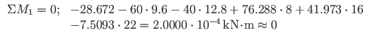
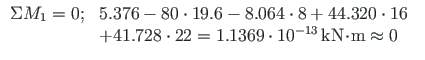
Testing a static equilibrium for the beam
Consider now a static equilibrium of the beam shown in Fig. 3.25.
Let us project the forces onto the Z-axis:
#=================================================================================
 Element displacements and forces determined by transfer matrix
#=================================================================================
Displacements and forces of element no 1 of length 8.000 m
The element is divided into 5 parts
 displacement w - 0.000e+00  2.753e-04  8.258e-04  1.239e-03 1.101e-03 -1.735e-18
 rotation    fi - 0.000e+00 -3.011e-04 -3.441e-04 -1.290e-04 3.441e-04  1.075e-03
 shear force  Q -   2.016      2.016      2.016      2.016      2.016      2.016
 moment force M -  -5.376     -2.150      1.075      4.301      7.526     10.752
----------------------------------------------------------------------------
Displacements and forces of element no 2 of length 8.000 m
The element is divided into 5 parts
 displacement w - 0.000e+00 -2.202e-03 -4.542e-03 -5.780e-03 -4.679e-03  0.000e+00
 rotation    fi - 1.075e-03  1.548e-03  1.247e-03  1.720e-04 -1.677e-03 -4.301e-03
 shear force  Q -  -6.048     -6.048     -6.048     -6.048     -6.048     -6.048
 moment force M -  10.752      1.075     -8.602    -18.278    -27.955    -37.632
----------------------------------------------------------------------------
Displacements and forces of element no 3 of length 6.000 m
The element is divided into 5 parts
 displacement w -  0.000e+00  5.965e-03  1.133e-02 1.280e-02 8.200e-03 -3.469e-18
 rotation    fi - -4.301e-03 -5.181e-03 -3.305e-03 1.326e-03 5.832e-03  7.334e-03
 shear force  Q -  38.272     38.272     38.272     38.272    -41.728    -41.728
 moment force M - -37.632      8.294     54.221    100.147     50.074      0.000
----------------------------------------------------------------------------
Displacements and forces of element no 4 of length 2.000 m
The element is divided into 5 parts
 displacement w - 0.000e+00 -2.934e-03 -5.868e-03 -8.801e-03 -1.174e-02 -1.467e-02
 rotation    fi - 7.334e-03  7.334e-03  7.334e-03  7.334e-03  7.334e-03  7.334e-03
 shear force  Q -   0.000      0.000      0.000      0.000      0.000      0.000
 moment force M -   0.000      0.000      0.000      0.000      0.000      0.000
----------------------------------------------------------------------------
Forces of element  1  at x = 4.000
 displacement w -  1.07520e-03
 rotation    fi - -2.68800e-04

 shear force  Q -  2.01600
 moment force M -  2.68800
-----------------------------------
Forces of element  2  at x =  1.599
 displacement w - -2.20201e-03
 rotation    fi -  1.54829e-03
 shear force  Q - -6.04800
 moment force M -  1.07521
-----------------------------------
Forces of element  2  at x = 4.000
 displacement w -  -5.37600e-03
 rotation    fi -   8.06400e-04
 shear force  Q -  -6.04800
 moment force M - -13.44000
-----------------------------------
Forces of element  2  at x = 4.800
 displacement w -  -5.78028e-03
 rotation    fi -   1.72032e-04
 shear force  Q -  -6.04800
 moment force M - -18.27840
-----------------------------------
Forces of element  3  at x = 3.600
 displacement w -    1.27955e-02
 rotation    fi -    1.32557e-03
 shear force  Q -  -41.72800
 moment force M - 100.14720
-----------------------------------
=====================================
 Minimum-maximum bending moments
=====================================
 No     x      Mq    Mmax    Min
-------------------------------------
   1   0.00 -62.53 -33.86  -67.91
   2   0.80 -28.41  -8.34  -32.18
   3   1.60  -1.97   9.50   -4.12
   4   2.40  16.79  19.65   16.25
   5   3.20  27.87  28.94   22.13
   6   4.00  31.27  33.95   16.93
   7   4.80  26.99  31.29    4.05
   8   5.60  15.03  20.94  -16.51
   9   6.40  -4.61   2.91  -44.75
  10   7.20 -31.93 -22.79  -80.68
  11   8.00 -66.93 -56.18 -124.28
  12   8.80 -31.05 -25.14  -35.97
  13   9.60  -2.85  45.74   -2.85
  14  10.40  17.67  69.61   13.90
  15  11.20  30.51  86.88   21.91
  16  12.00  35.67  96.47   22.23
  17  12.80  33.15  98.38   14.87
  18  13.60  22.95  60.60   -0.17
  19  14.40   5.07  15.15  -22.89
  20  15.20 -20.49 -20.49  -70.77
  21  16.00 -53.73 -53.73 -136.42
  22  16.60 -31.32 -31.32  -86.54
  23  17.20 -13.23  -4.93  -49.27
  24  17.80   0.55  31.80  -30.99
  25  18.40  10.00  64.22  -17.03
  26  19.00  15.13  92.32   -7.39
  27  19.60  15.95 116.09   -2.08
  28  20.20  12.44  87.55   -1.08
  29  20.80   4.61  54.69   -4.40
  30  21.40  -7.53  17.50  -12.04
  31  22.00 -24.00 -24.00  -24.00
  32  24.00   0.00   0.00    0.00
----------------------------------
![\includegraphics[width=132mm]{joonised/ESTjatkvtala_en.eps}](img404.png)

![\includegraphics[width=140mm]{joonised/ESTjatkvtalaKJS.eps}](img405.png)
![\includegraphics[width=132mm]{joonised/jatkvtala5cESTm.eps}](img406.png)


![\includegraphics[width=130mm]{joonised/jatkvtala5bESTm.eps}](img410.png)


![\includegraphics[width=130mm]{joonised/jatkvtala5aESTm.eps}](img413.png)


![\includegraphics[width=0.99\textwidth]{joonised/Suurimad_MtsenV.eps}](img416.png)
![\includegraphics[width=0.82\textwidth]{joonised/TalaEST_en.eps}](img417.png)
![\includegraphics[width=0.75\textwidth]{joonised/TalaEST_sparse.eps}](img418.png)