Next: 1.2 Basic equations for Up: 1. Introduction Previous: 1. Introduction
The motion of a frame element is composed of rigid body translation, rigid body rotation, and strain producing deformations (see [PW94] p. 171). Let us now apply a local coordinate system (x, z) to the frame element shown in Fig. 1.1. (X, Z) is the global coordinate system. We consider the right-handed coordinates shown in Fig. 1.3 and Sign Convention 2 in Fig. 1.2.
We determine first the rigid body translation and rigid body rotation at the ends of the frame element shown in Fig.1.1:
 ,
,  - axial displacements at the beginning and at the end of the element, respectively;
 ,
,  - transverse displacements at the beginning and at the end of the element, respectively;
 ,
,  - rotation at the beginning and at the end of the element, respectively.
The rigid body displacements and rotations of the element shown in Fig. 1.1 can be large.
The basic coordinate system (x*, z*) in Fig. 1.5 rotates and translates together with the element [Suz00], [YSK08]. With respect to this basic coordinate system, only local strain producing deformations remain (see [PW94] p. 171).
![\includegraphics[width=65mm]{joonised/vptelg.eps}](img30.png)
|
| The finger points in the positive direction of the respective axis. Each arrow is labeled by an axis letter in the sequence x, y, z or 1, 2, 3. |
The deformations (internal displacements [KHMW10], [KHMW05])  and
and  in Fig. 1.5 can be determined
by the unit load method using the material law relationships [PW94].
in Fig. 1.5 can be determined
by the unit load method using the material law relationships [PW94].
We proceed decomposing the deformations  and
and  into the effects of
the shear force and bending moment
into the effects of
the shear force and bending moment  :
:
 - bending stiffness of the element,
 - shear stiffness of the element.
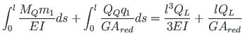
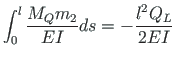
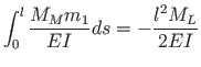
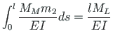
Now we consider again the moment diagrams in Figs. 1.4 and 1.6,
and apply the unit load method for finding  and
and
 :
:
The axial deformation of the element
 - axial force at the element end,
All deformations of the frame element arranged in matrix form:
Now we consider a frame element (shown in Fig. 1.8) with no loads applied between the ends.
We shall now assemble Eqs. (1.1), (1.8), (1.9)
into a matrix of basic equations
 ,
,
 are the vectors of displacements and forces
at the end and at the beginning of the element, respectively,
are the vectors of displacements and forces
at the end and at the beginning of the element, respectively,
 is the transfer matrix (Sign Convention 2):
andres
![\includegraphics[width=95mm]{./joonised/svarrasESTr.eps}](img21.png)
![$\displaystyle \left[\begin{array}{c}
u_{L} \\
w_{L} \\
\varphi_{L}
\end{array...
...ight]
\left[\begin{array}{c}
u_{A} \\
w_{A} \\
\varphi_{A}
\end{array}\right]$](img22.png)
![\includegraphics[width=120mm]{joonised/margikoke.eps}](img29.png)
![\includegraphics[width=135mm]{joonised/kinnisiireMF.eps}](img31.png)
![$\displaystyle \left[\begin{array}{c}
\Delta w \\
\Delta \Theta
\end{array}\rig...
...{Q} + \Delta w_{M} \\
\Delta \Theta_{Q} + \Delta \Theta_{M}
\end{array}\right]$](img35.png)
![\includegraphics[width=120mm]{./joonised/svarrasESTrbas.eps}](img36.png)
![\includegraphics[width=135mm]{joonised/kinnisiireFM.eps}](img37.png)


![$\displaystyle \left[\begin{array}{c}
\Delta w \\
\Delta \Theta
\end{array}\rig...
... }}
{\normalfont { \left[\begin{array}{c}
Q_{L} \\
M_{L}
\end{array}\right] }}$](img51.png)
![\includegraphics[width=135mm]{joonised/kinnisiireQq.eps}](img52.png)

![$\displaystyle \left[\begin{array}{c}
\Delta u_{L} \\
\Delta w \\
\Delta \Thet...
...malfont {\left[\begin{array}{c}
N_{L} \\
Q_{L} \\
M_{L}
\end{array}\right] }}$](img55.png)
![\includegraphics[width=90mm]{./joonised/talaREMo.eps}](img56.png)
![$\displaystyle \left[\begin{array}{c}
N_{L} \\
Q_{L} \\
M_{L}
\end{array}\righ...
...ray}\right]
\left[\begin{array}{c}
N_{A} \\
Q_{A} \\
M_{A}
\end{array}\right]$](img57.png)
![$\displaystyle \left[\begin{array}{c}
\Delta u_{L} \\
\Delta w \\
\Delta \Thet...
...malfont {\left[\begin{array}{c}
N_{A} \\
Q_{A} \\
M_{A}
\end{array}\right] }}$](img58.png)
![$\displaystyle \mathbf{Z_{L}} =
\left[\begin{array}{c}
u_{L} \\
w_{L} \\
\varp...
...{A} \\
\varphi_{A} \\
\ldots \\
N_{A} \\
Q_{A} \\
M_{A}
\end{array}\right]$](img62.png)
![$\displaystyle \mathbf{U} = {\normalsize { \left[ \begin{array}{ccccccc}
1 & 0 &...
... 0 & - 1 & 0 \\
0 & 0 & 0 & \vdots & 0 & - l & -1
\end{array} \right] }}
\quad$](img64.png)
![$\displaystyle \mathbf{U} = \left[ \begin{array}{ccc}
Rigid \;\; body & \vdots &...
...gs, & \vdots & \\
foundations, \;\; etc.) & \vdots &
\end{array} \right]
\quad$](img65.png)